|
Background Material
[Note: To do a 7-day lesson on the Sun-Earth connection, which was briefly described in the previous story section, we recommend using the LHS GEMS guide, “Living with a Star.” See the “Resource” section at the end of this guide.]
More Information about the STEREO/IMPACT Experiment
The STEREO mission consists of two spacecrafts positioned on either side of Earth in its orbit around the Sun. The spacecrafts study the Sun, the Solar Wind, and the interplanetary magnetic field (IMF) from two perspectives in space. This makes it possible to make 3-dimensional (3-D) images, as depicted in Figure BSW.1. Since the spacecrafts are physically located in the Solar Wind they can make direct measurements of its magnetic field using a magnetometer that detects the strength and direction of a magnetic field. The spacecrafts have many instruments aboard that use electricity to operate. As has been discussed, these electronic components of other instruments will produce magnetic fields of their own. These magnetic fields will interfere with the magnetometers’ measurements of the Solar Wind’s magnetic field (the IMF).
The engineers who designed the magnetometer experiment had to come up with a way to allow the magnetometers to measure the IMF, uncontaminated by the fields created by the spacecrafts’ own electronics. NASA engineers came up with a two-fold design. The inside of the boom is a telescoping “stacer” made out of metal that is wrapped around itself, much like a rolled up poster that is taped shut. The only way for the stacer to move is to push out, making a longer cylinder, like a rolled poster would if you pulled on each end of the cylinder. This is the same mechanism as a Chinese yo-yo. The stacer protects the wires that are wound together to go out to the magnetometer.
Outside of the stacer is another telescoping boom with individual cylinders tucked within each other. When the boom deploys in space, each section moves out along runners with little tiny wheels (see the photographs in the Boom Photograph section below) until each section locks into place with several pins. This outside boom keeps the magnetometers far away from the spacecraft. The boom must be fairly stiff (rigid) and will house several other instruments beside the magnetometers.
See the Resource Section to find out more about the STEREO mission and the IMPACT instrument suite.
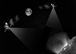
Figure BSW.1 An artist’s rendition of how the STEREO satellites will orbit the Sun with Earth. They will observe the Sun’s surface and take measurements of the solar wind flowing past the satellites. Note that this image is not to scale: the Sun is much farther away and larger than indicated here and the spacecrafts are vastly smaller than Earth.
Questions and Answers with Paul Turin on Boom design:
Paul Turin is an engineer who works on designing and building booms for NASA spacecraft. He works at the University of California at Berkeley, and by answering our questions, he helped to design the third session in this lesson plan. Here are the questions we asked, and some of his answers.
In terms of strength, stiffness, and end-play, which is most important in the engineering of the boom design?
In launch, the strength and stiffness of the boom are the most important. In actual operation in space, that the boom is stiff and play-free (does not sway about) is most important, and strength does not usually matter. In relation to the spacecraft, stiffness and lack of play are important to think about in this way: if the satellite moves, you don’t want the boom to bend or to move (to some specified accuracy). This means that once the boom is deployed from the spacecraft, it will remain in only one position relative to the spacecraft. You want the boom to end up in a known position and to not move from that position because an instrument, such as a magnetometer, is sitting near the end of the boom and scientists need to know the exact location and orientation of that instrument.
Have the kind of materials used for booms changed over the past years?
20-30 years ago, booms were made out of aluminum because aluminum is light, which is important for the cost of launching the satellite, and because it is strong and stiff. Now, booms are usually made of carbon fiber because of its versatility and because it is stronger and stiffer than metals. Carbon fiber can be molded to many different shapes. It starts as a cloth-like fiber and is then put in epoxy and wrapped around a form, often made out of metal, such as a cylinder. As the epoxy-covered carbon fiber hardens, it takes on the shape of the form around which it is wrapped. Another benefit is that a shape made of carbon fiber that has the same stiffness and strength as an aluminum one will be considerably lighter.
What are the main difficulties in designing a boom?
Deploying a boom is one of the most difficult tasks. How can we deploy something so long and stiff without much play? The design of any joints in the boom is critical to its performance. When the joint latches close, it must not be able to move again – the boom needs to act as if it were made of a single piece of material.
How are such stiff booms deployed?
In the STEREO IMPACT boom, for example, there is a compressed spring called a stacer inside and when the time comes, the boom is deployed by allowing the spring to push the telescoping boom out. This boom has several nesting tubes with three grooves in each tube (see picture) and little wheels that follow along the grooves. When each tube gets to the end of the next larger tube, pegs fall into holes and the boom becomes long, play-free, and stiff.
Are the currents carried in the wires out to the end of the boom ever a problem for magnetometer measurements?
Not if they are handled properly. The wires are twisted pairs and so their magnetic fields tend to cancel each other out. Also there is the metal stacer that shields the wire. This stacer is a sheet of metal rolled up tight enough that when released, pushes out into a long tube, generating the force to deploy the boom as it does so. It is very similar to a Chinese yo-yo made out of a beryllium-copper alloy.
How long does it take to design and build a boom?
The entire process typically takes three years from concept to delivery of the boom to the satellite. First, a concept of a design is considered. Then certain ideas that are new are tested by building parts to see if the idea is feasible. Then a beginning design is finalized and an ETU (Engineering Test Unit) unit is built. Any changes that are deemed necessary as a result of the ETU testing are made, and then a proto-flight unit is built (this becomes a flight spare). If that works, then the flight units are built, tested and delivered.
What are some of the problems that occur while building a boom?
There are always many problems. For example on the STEREO-IMPACT boom problems arose when we were trying to create the grooves in the tubes. We had a hard time getting the carbon fiber cloth to stay in the grooves in the metal form while wrapping the cloth around it. The grooves had to be nice and smooth so the wheels would ride smoothly in them, and it took many tries to work out how to get them to come out smooth enough. Carbon fiber as a material is difficult to use in general because it comes as a cloth that then you put a glue-like substance on it to make it harden to the shape you want. This becomes a sticky situation, literally!
Photographs of the STEREO/IMPACT boom
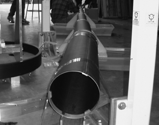
The parts of the boom laid out in a telescoping fashion
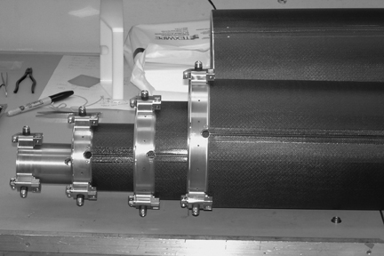
A close-ip of the wheels and pegs on the engineering model
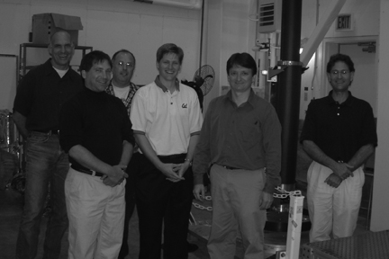
The STEREO/IMPACT boom team:
Ken McKee, Bill Donakowski, Mario Marckwordt, Jeremy McCauley, Paul Turin, Robert Ullrich
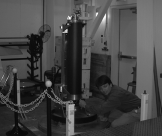
Paul is getting ready to deploy the boom...
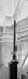
And the boom goes up, up, up until it snaps completely into place and is fully deployed. |
|
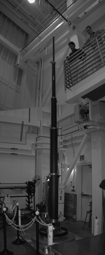
The boom deployed. Weights can be seen at the top. They are used to counter-balance the force on the booms due to gravity since in space the spacecraft will be far from Earth’s gravity when the boom is deployed. |
- back to top -
|